Wind Turbine Simulation as a Real-Time System
On this page you will find the documentation for the Process Programming internship on the topic: "Simulation of a Wind Turbine System".
In 2003, I worked on this project together with a fellow student and developed a simulation for the operation of a wind turbine, based on the multi-threading real-time system RTKERNEL (FH-Wedel, Summer Semester 2003).
1. Table of Contents
2.2 Program Installation and Start-Up 3
2.3.1 The Graphical User Interface. 4
2.3.2 User Control and Program Flow. 4
3.1 Development Configuration. 5
3.2 Problem Analysis and Implementation. 6
3.3 Overview and Description of All Tasks. 6
3.4 Intertask Communication and Synchronization. 7
3.5 The Data Structures Used. 7
3.6 General Description of the Program Flow. 9
4.1 Original Assignment for Process Programming 1, SS 2003. 11
2. User Manual
2.1 Operating Conditions
The following hardware and software components are required to run the program:
|
Hardware |
|
|
Software |
|
2.2 Program Installation and Start-Up
To start the simulation, the program must first be installed.
To install the program, the complete „Windrad“ directory must be copied from the installation CD to the hard drive. The program can then be started there by launching „RADK.EXE“. If necessary, the write-protection attribute of the file „log.txt“ must also be removed, if the file manager did not already do this automatically during copying.
The program can be easily uninstalled again by deleting the copied directory (including all subfiles).
Starting the program directly from the CD is not possible, since no write access (for creating the log file) is permitted on this medium.
2.3 Operating Instructions
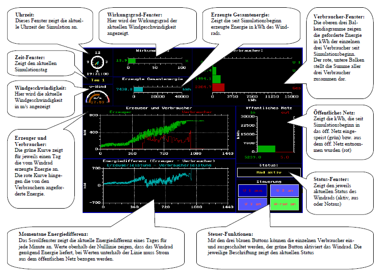
In this simulation of a wind turbine system, the screen provides a complete overview of all relevant data as well as buttons for controlling the wind turbine and consumers.
2.3.1 The Graphical User Interface
The image below shows the program's graphical user interface after a successful start. The main window is divided into eleven smaller windows with blue borders, each displaying the information described, so that the simulation can be monitored at any time.
2.3.2 User Control and Program Flow
After launching and starting the program („RADK.EXE“), the wind turbine simulation starts automatically. It can be terminated at any time by pressing the „Escape“ key. After four simulation days, the program stops and displays the last calculated data until the program is closed.
Using the mouse, each individual consumer as well as the wind turbine can be switched on and off by clicking the buttons. The respective button label indicates the current state. In addition, it is possible to shut down the wind turbine immediately using the „Print“ key. This emergency stop switch has the highest priority and takes effect immediately after the key is pressed. Pressing it again resets the emergency stop switch.
2.4 Result Log
To see the result of the simulation, simply look at the log file. Throughout the entire simulation, all important states are logged and can subsequently be found in the log file. For each minute, the status of the wind turbine can be seen (whether it was switched on/off or whether it was deactivated by the emergency stop switch). Based on the specified difference, it is possible to determine at any time whether the wind turbine fed energy into the public grid or drew energy from it. The total difference then shows the cumulative value and indicates whether the use of the wind turbine is economically viable or not. In addition, the log file contains the respective status (switched on/switched off) of the three consumers (V1, V2 and V3) at every point in the simulation. The following image shows an excerpt from the log file:
Day: █ Status: █ Difference: █ Total Difference: █ V1 █ V2 █ V3
____________________________________________________________________
1 0:49 a.m. █ Turbine off █ 0.00 kW █ 37.32 kWh █ Off █ Off █ Off
1 0:50 a.m. █ Turbine off █ 0.00 kW █ 37.32 kWh █ Off █ Off █ Off
1 0:51 a.m. █ Turbine off █ 0.00 kW █ 37.32 kWh █ Off █ On █ Off
1 0:52 a.m. █ Turbine off █ 0.00 kW █ 37.32 kWh █ Off █ On █ Off
1 0:53 a.m. █ Turbine off █ 0.00 kW █ 37.32 kWh █ Off █ On █ Off
1 0:54 a.m. █ Turbine off █ 0.00 kW █ 37.32 kWh █ Off █ On █ Off
1 0:55 a.m. █ Turbine off █ 0.00 kW █ 37.32 kWh █ Off █ On █ Off
1 0:56 a.m. █ Turbine off █ 0.00 kW █ 37.32 kWh █ Off █ On █ Off
1 0:57 a.m. █ Turbine active █ 116.48 kW █ 39.26 kWh █ Off █ On █ Off
1 0:58 a.m. █ Turbine active █ 115.05 kW █ 41.17 kWh █ Off █ On █ Off
1 0:59 a.m. █ Turbine active █ 125.26 kW █ 43.26 kWh █ Off █ On █ Off
1 1: 0 a.m. █ Turbine active █ 64.01 kW █ 44.33 kWh █ Off █ On █ Off
1 1: 1 a.m. █ Turbine active █ 68.07 kW █ 45.46 kWh █ Off █ On █ Off
1 1: 2 a.m. █ Turbine active █ 70.58 kW █ 46.64 kWh █ Off █ On █ Off
1 1: 3 a.m. █ Turbine off █ 0.00 kW █ 46.64 kWh █ Off █ On █ Off
1 1: 4 a.m. █ Turbine off █ 0.00 kW █ 46.64 kWh █ Off █ On █ Off
1 1: 5 a.m. █ Turbine off █ 0.00 kW █ 46.64 kWh █ Off █ On █ Off
1 1: 6 a.m. █ Turbine off █ 0.00 kW █ 46.64 kWh █ Off █ On █ Off
1 1: 7 a.m. █ Turbine off █ 0.00 kW █ 46.64 kWh █ Off █ On █ Off
1 1: 8 a.m. █ Turbine off █ 0.00 kW █ 46.64 kWh █ Off █ On █ Off
1 1: 9 a.m. █ Turbine active █ 75.15 kW █ 47.89 kWh █ Off █ On █ Off
1 1:10 a.m. █ Turbine active █ 133.58 kW █ 50.12 kWh █ Off █ On █ Off
1 1:11 a.m. █ Turbine active █ 92.99 kW █ 51.67 kWh █ Off █ On █ Off
1 1:12 a.m. █ Turbine active █ 118.64 kW █ 53.65 kWh █ Off █ Off █ Off
3. Programming Manual
3.1 Development Configuration
The development of „Fighter“ was carried out using the following software:
- Operating system: MS-DOS
- Programming environment: Borland Pascal 7 including the RTKernel real-time environment
- UltraEdit-32 version 10.0 for editing the source code
3.2 Problem Analysis and Implementation
The implementation of the simulator places several demands on the developers. The most important components of the program are:
- The meaningful division of the different program components into parallel processes (tasks)
- The synchronization and communication of the tasks with each other (intertask communication)
- The graphical display of the control room using the RTGraphics toolbox.
- The implementation of the „emergency stop switch“ through an Interrupt Service Routine
- A well-structured and clearly organized log file
3.3 Overview and Description of All Tasks
- Task_Wind
- This task provides the current wind speed. First, the current simulation time is fetched from the time task. Then the current nominal wind speed is calculated using linear interpolation of the values specified in the assignment for the previous and next full hour, and is then modified to the actual value by a random deviation of ±10%.
- Task_Zeit
- This task provides the current simulation time. The duration of the simulation is also defined here, with the task loop running for exactly 5760 minutes (4 days). Since synchronization originates from this task, proper completion of the simulation and correct termination of all other tasks is ensured. The time itself is calculated from the number of RTKernel system ticks since the simulation started. The timer interval was set to 10 ms during program initialization, which corresponds to 0.1 minute in simulation time. Therefore, a delay of 10 ticks must occur at the end of each loop iteration so that the correct simulation duration is maintained.
- Task_Windrad
- Control of the wind turbine → determination of the currently generated power. At the beginning of each loop iteration, this task first checks whether the emergency stop mailbox is full. It then retrieves the status of the „regular“ switch. If the emergency stop is active or the regular switch is off, the task returns the power value 0. Otherwise, it checks whether the wind speed is too high or too low, in which case 0 would also be returned. Under normal conditions, the currently generated power in kW is returned.
- Task_Verbraucher
- Determination of the power for each individual consumer. The special feature of the consumers is that the same task routine is used for each one. In order for each consumer to still be uniquely identified, the consumer number is extracted from the task name during initialization and stored in the variable ‚Index’. Each consumer has an interval of time during which the energy demand is constant. This time and the power itself are determined randomly. When the time has expired, the time and power are recalculated in the next loop iteration.
- Task_Verteiler
- Coordination of generator and consumer power and calculation of the total energy. In this task, the energy demand of each individual consumer is mainly processed first. It must be taken into account that the order in which the messages are sent by the three consumers is not fixed. Therefore, this information is included in the message. In addition, most of the information displayed on the screen is calculated in this task.
- Task_Warte
- Provides user interaction and screen output. This task represents, so to speak, the interface between user control and the rest of the program, since all user inputs are processed in this task. (Only the emergency stop function is processed directly by the wind turbine task, and the status is then sent from the wind turbine to the control room.) The handling of the log file is also managed exclusively in this task. At the end of each run, all graphics windows are updated by passing the newly displayed values to the drawing routines.
3.4 Intertask Communication and Synchronization
Intertask communication was essentially implemented using two concepts: mailboxes and message passing.
With message passing, the sender and receiver tasks must be synchronized, i.e. both tasks must be ready to send and receive at the same time. If this is not the case, the task that is already ready blocks until the other one is also ready, so that the transfer can take place.
The mailbox concept is structured in such a way that the tasks do not necessarily have to be synchronized during data transfer, since a (freely definable) number of ‚slots’ (in the present program, each mailbox always contains only one slot) is available – memory space suitable for the data type of the data to be sent. When a data record is to be sent, it is placed into the mailbox by the sender task. The receiver task reads this data record from the mailbox and then deletes it there. If a data record is to be received while the mailbox is empty, the receiver task blocks until the mailbox is filled with a data record. The same applies to the sender task when the mailbox is full.
However, in both concepts synchronization can be somewhat „relaxed“ by specifying that a task should not block if the other task is not ready for transfer or if a mailbox is empty or full. With this method it is possible to query whether a transfer has taken place or not. In the present program, this method was used when retrieving data from the emergency stop mailbox, since this mailbox is only filled when the ISR of Int5 is called.
3.5 The Data Structures Used
|
Type: |
Description:
|
|
TMin = 0..59; TStd = 0..23; TTag = 0..3; TUhrzeit = record Tag : TTag; Std : TStd; Min : TMin; end; |
- Defines 60 minutes for one hour - Defines 24 hours for one day - Simulation duration: 4 days Stores the current simulation time, i.e. which day, which hour, which minute |
|
TWind = array[0..4*24-1] of real; |
Array for wind speed constants; 4 days with 24 hours each are specified directly, and the values in between are linearly interpolated. |
|
TWirk = array[5..25] of real; |
Array for efficiency constants |
|
TVerbraucher = record Pmin, Pmax : longint; Tmin, Tmax : longint; end; TVerbrArr = array[1..3] of TVerbraucher; |
For storing the time interval and power interval of the three consumers. Pmin/Pmax: Minimum and maximum value of the consumer's required power Tmax/Tmax: Minimum and maximum duration of the power demand (how long a value is requested) |
|
TVerbBox = record Energie : real; Num : byte; end; |
Stores the currently consumed energy and the corresponding index number of the respective consumer (this „Num“ value is important in order to distinguish the individual tasks, since all of them use the same task function. |
|
TWPBox = record vWind : real; wirk : real; EWind : real; keinnotaus : boolean; end; |
Stores all data sent from the wind turbine task to the control room (wind speed, active power, wind energy, and the status of the emergency stop switch). This type is used for the mailbox. |
|
TVerbrAnzeige = array[1..4] of real; |
Stores the values displayed in the consumer window (4 = total consumption) |
|
TEPBox = record EVerbraucher : TVerbrAnzeige; PVerbraucher : real; PErzeuger : real; Differenz : real; ENetzrein : real; ENetzraus : real; end; |
Stores all data sent from the distributor task to the control room. The control room is responsible for the output function and must therefore have access to all calculated data. |
|
TBtnState = array [0..3] of integer; |
Stores the states of the four buttons (whether pressed or not pressed) |
|
Tbuffer = array [1..3] of real; |
Stores the last three wind speeds for hysteresis calculation (the wind turbine should only switch on or off after the threshold has been exceeded three times) |
|
CWind : TWind = ( {Day1} 6,6.5,6.7,6.7,6.8,7,8,9,9.5,10,10.2, 10.5,10.7,11,12,13,14,17,18,18,16,15.5, 15,15, {Day2} 15,14,13.5,13,12,12.2,12.5,12,12.3,12, 11, 10,9,9,8,7.5,7,6,5.8,5.4,5,3,2,2, {Day3} 2,2.5,3,3.5,4,4.2,4.5,5,5.3,6,7,8,7.7, 7,6,5,5.4,6,7,8,9,9,7,6, {Day4} 7,8,9,9.5,10,10.2,10.5,10.7,11,12,13, 14,17,18,20,23,26,25.5,25,23,22,20, 19,17 ); |
Constant efficiency values at different wind speeds from the weather laboratory for four simulation days. There are 24 average values, one for each hour of the day. The values for the minutes are linearly interpolated from these. |
|
CWirk : TWirk = ( 26.2,37.2,41.9,43.7,44,43.3,40.9, 37,32.5,27.2,22.3,18.5,15.4,12.9, 11,9.3,8,7,6.1,5.2,4.5 ); |
This constant array contains the efficiency values for the corresponding wind speeds. It starts at a wind speed of 5 m/s and increases in whole-number steps up to the value for a wind speed of 25 m/s. This has the advantage that the efficiency can be indexed directly by the wind speed. |
|
CVerbraucher : TVerbrArr = ( (Pmin:20000; Pmax:200000; Tmin:2; Tmax:10), (Pmin:40000; Pmax:100000; Tmin:10; Tmax:30), (Pmin:100000; Pmax:250000; Tmin:5; Tmax:20) ); |
Constant values for the time and power interval specifications of all three consumers |
|
CTickDelay = 10; CWindrad = 0.8495; CWindflaeche = 1452; CFensterAnzahl = 11; CLogFile = '.\log.txt'; |
Sets the simulation speed (time delay) Proportionality factor for calculating wind energy Area of the wind turbine Number of graphics windows in the screen output Filename of the log file |
3.6 General Description of the Program Flow
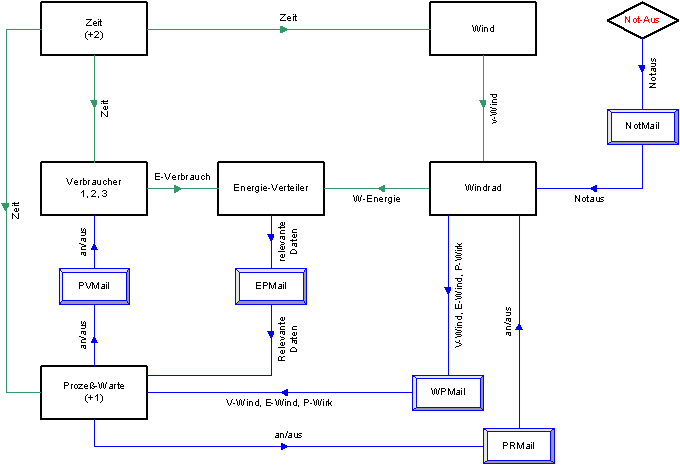
Legend of the objects:
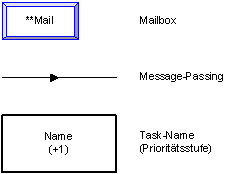
The following describes the general flow of one simulation minute:
In the present program, synchronization originates from the time task, which defines the simulation speed. From there, messages containing the current time information are sent to the wind field task, to all consumers, and to the control room. The wind field task sends a message with the wind speed to the wind turbine task, but only after the time has been received by the wind field task. The wind turbine task in turn sends a message with the generated energy to the distributor task. After receiving the time and querying the status from the control room, each consumer also sends a message to the distributor with the requested energy. Once the distributor has received all messages, all required data is calculated in this task and sent to the control room via mailbox. Likewise, the information from the wind turbine task is sent to the control room via mailbox. For intertask communication with the control room, mailboxes are useful because programming becomes somewhat more flexible with the same effectiveness, since otherwise user input could possibly lead to deadlocks.
The wind turbine task may receive a message from the ISR of the emergency stop switch. If a message is received, the emergency stop switch is toggled.
3.7 ISR Flow
To provide the user with a safe and fast way to switch off the wind turbine immediately (e.g. in the event of a fault), the program triggers an interrupt with the highest priority when the „Print“ key is pressed.
In order for the program to respond to the interrupt, it has its own Interrupt Service Routine, which is executed when the interrupt is triggered. So that DOS knows this routine and can respond to it, the old interrupt vector 5 is first saved at the beginning of our program and then redirected to our ISR. To avoid deadlocks while redirecting the vector, this is done in a semaphore-protected section. When the key is pressed and the interrupt is thus triggered, our ISR is called. The ISR first terminates the critical section or semaphore; afterwards, the routine sends a message via mailbox to the wind turbine task, which immediately stops the calculation or shuts down the wind turbine (the value zero for generated energy is sent to the energy distribution).
When the program is terminated, the old saved interrupt vector 5 is restored, since our ISR no longer exists.
3.8 Priority Assignment
The program uses a total of eight tasks. In order for synchronization between them to work properly, it is important that the individual tasks have different priorities. Otherwise, some tasks would block and the program would stop in an endless loop. The following table shows the different priorities of all tasks used and explains why this assignment is important:
|
Task |
Priority |
Description |
|
Timer |
MainPriority+2 |
To ensure a reliable and synchronous simulation clock, it must be guaranteed that the timer task is always called, since it provides the current time. |
|
Control Room |
MainPriority+1 |
The control room has a higher priority because it handles the control function and output on the screen. It must be able to receive the data from the wind turbine and energy distributor so that they are not blocked for too long and the simulation does not stop. |
|
Wind |
MainPriority |
All of these tasks have the same priority because, due to the implemented message passing in a chain, it is always ensured that this chain of tasks waits for the data from the „predecessor“ and then sends it onward. |
|
Wind Turbine |
MainPriority |
|
|
Energy Distributor |
MainPriority |
|
|
Consumers 1,2,3 |
MainPriority |
Since sudden malfunctions can occur during the operation of a wind turbine, it is very important for safety that there is always a way to stop the turbine immediately. In our simulation, this function is performed by the „interrupt-controlled“ emergency stop switch. Since an interrupt always means an immediate interruption of the running program, shutting down in this way is a safe option. The „emergency stop interrupt“ therefore effectively has the highest priority!
4. Appendix
4.1 Original Assignment for Process Programming 1, SS 2003
4.2 Program Source Code
Comments 0
Write new comment: